Singularity Design
Published on
Due to technological progress and continuous innovation, new ideas and concepts are emerging that can redefine existing approaches to design and development. One such concept, which I am currently developing, is “Singularity Design”. This paradigm aspires to streamline the design process by generating a project or a part solely from user requirements, without necessitating continuous user effort. The vision for this paradigm includes a range of promising features: the elimination of connections, swift visualization of results, integrated simulation-driven design, potential acceleration of innovation, and a holistic view of the system at all stages of design. Predicated on an iterative method, Singularity Design aims to meet the complex demands of modern engineering projects in a dynamic and efficient way.
New Paradigm
The Singularity Design paradigm, though still in its nascent stages, presents a potential turning point in the engineering industry. This pioneering approach to create a design exclusively from user requirements, can potentially simplify and enhance the design process.
A key prospective advantage of this paradigm lies in its scalability. It has the potential to be employed at all design levels, from routine operations during part modeling to the final stages of an entire system’s design. This scalability permeates every phase of the design process, from the initial design stage to the implementation of modifications during production.
The integration of digital twins in the Singularity Design paradigm could facilitate real-time alterations to the design already in production, taking into account manufacturing capabilities and constraints. This could pave the way for more efficient manufacturing processes, as designs would be optimized for production right from the beginning.
Moreover, the ability to maintain a holistic view of the system throughout the design stages fosters the emergence of complex structures within the project. This emergence isn’t accidental; it’s a byproduct of a design philosophy that values the sum of all parts, not just the individual components. Such a comprehensive approach is poised to significantly enhance the functionality and reliability of the end product, bringing it into closer alignment with the user’s demands and expectations.
Another important benefit of this paradigm is the elimination of design errors when implemented correctly. Design errors are an unfortunate but common occurrence in the engineering industry, often resulting from a variety of factors such as miscommunication, lack of understanding of requirements, or simple human error. These mistakes can have significant implications, particularly for large projects where even minor errors can lead to substantial cost overruns, delays, and in some cases, safety concerns. Furthermore, human errors can often lead to a cascade of issues, where one mistake can trigger a series of subsequent errors, further exacerbating the problem.
To mitigate these risks and enhance design quality, the concept of systems engineering was introduced. Systems engineering is a multidisciplinary approach that focuses on how to design and manage complex systems over their life cycles. It aims to ensure that all likely aspects of a system are considered and integrated into a whole. This approach has been instrumental in reducing errors, improving design quality, and ensuring that all components of a system work together seamlessly.

A crucial aspect of systems engineering, particularly in Model-Based Systems Engineering (MBSE), is the design of interfaces. Interfaces serve as the junctions where different parts of a system interact, and their design can significantly impact the overall functionality and efficiency of the system. Poorly designed interfaces can lead to system failures, inefficiencies, and increased complexity. Therefore, careful attention to interface design is essential in MBSE to ensure that all parts of the system can interact effectively and that potential issues are identified and addressed early in the design process.
Systems engineering has been a significant step forward in managing the complexity of systems design. However, it is not without its limitations, particularly when it comes to modeling. In systems engineering, each part of the model has a distinct role and does not intersect with other elements. This separation is crucial for simplifying representation and development for engineers, but it also creates a rigid boundary between systems.

Interfaces, while essential for defining interactions between systems, also contribute to this rigidity. They create a strict border between systems to simplify their representation. However, this simplification and separation of functions can become a hindrance when synthesizing systems in new paradigms.
Nature, the most complex system designer, creates systems far more intricate than any human-made system. In natural systems, many components perform multiple functions simultaneously. For instance, bones not only provide structural support but also produce blood cells and store minerals. Similarly, the liver performs over 500 functions, including detoxification, protein synthesis, and the production of biochemicals necessary for digestion. This multi-functionality is a stark contrast to the single-function components typically seen in human-made systems.
The ability to consider all requirements simultaneously during design synthesis is crucial for creating efficient systems. However, MBSE often restricts this ability to maintain the expressiveness and visibility of the system, ensuring that all involved parties can understand the details. To increase complexity and achieve nature-like designs, we need to blur the borders of these details. This blurring makes the system extremely difficult to understand without being able to consider every piece of information at once.
This is where machines excel, and where a new paradigm, such as Singularity Design, can emerge. By utilizing the computational power of machines, we can navigate the complexity of these blurred boundaries and synthesize designs that can come close to the multifunctional systems found in nature. This approach could potentially pave the way for designs that are not only more efficient but also more resilient and adaptable to shifting requirements and conditions.
The Workflow
In the course of articulating my vision for Singularity Design, I’ve often been met with questions about who would stand to benefit from such a paradigm and why. Now that these questions have been addressed, it’s time to delve into the heart of this idea. While there are numerous questions surrounding the implementation of this paradigm (verification of designs produced by this system, cost to build it, etc.), given its conceptual stage, I will focus on the structural framework that should help achieve the goals previously outlined.
Here’s the outline of the workflow I envision
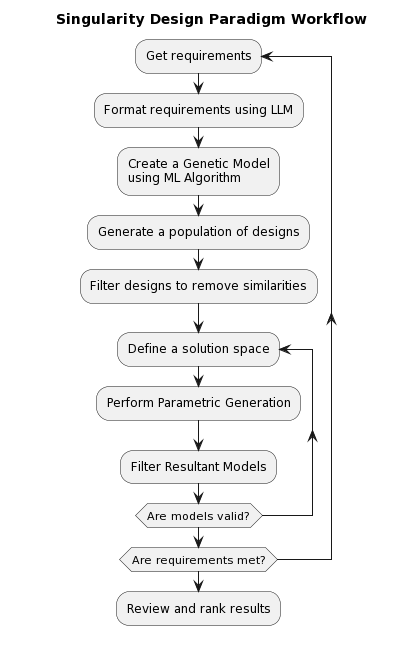
Requirements
Everything in Singularity Design is rooted in requirements. A common challenge for developers is aligning their vision of the product with that of the client. Singularity Design is not immune to this issue. However, a significant advantage of this paradigm is the ability to rapidly iterate the design without expending excessive resources. But this raises a critical question: what should requirements look like in this paradigm?
Should they take the form of a regular specification, or a standard form that the client fills out? Should there be a new programming language to describe it, or should we use existing languages like SysML? Or perhaps we could interact with the program dynamically, as if it were a human, similar to how we interact with “AI” chatbots?

The answer to all these options is a resounding YES. The key to this lies in the next component of the pipeline - a block that can interpret requirements in any form and translate them into a more structured format suitable for the next block. This block is designed to grasp the general idea of the requirements, regardless of their form, and parse it for the next block. This capability is made possible by leveraging the technology at the heart of AI assistants like ChatGPT, known as large language models (LLMs).
LLMs, in simple terms, are machine learning models trained on a vast amount of text data (if you want to dive deeper into this topic I recommend you to read this article What Is ChatGPT Doing … and Why Does It Work? by Stephen Wolfram). They learn to generate human-like text by predicting the next word in a sentence, given the previous words. This enables them to understand and generate text in a way that is coherent and contextually relevant.
In the context of Singularity Design, LLMs could potentially interpret and understand requirements in various forms, translating them into a structured format that can be used in the design process. To enhance the performance of LLMs for this task, fine-tuning could be a viable approach. Fine-tuning involves training the model on a specific task or domain, allowing it to better understand and generate text relevant to that task or domain. This could potentially improve the model’s ability to interpret and translate requirements, making it more effective in the Singularity Design paradigm.
My experimentation with ChatGPT has provided some interesting insights, particularly in its capacity to interpret requirements. Despite not being specifically trained for it, ChatGPT was able to generate a diagram for a conceptual pipe. I simply asked it to represent a pipe as a model using PlantUML syntax. After several interactions, during which I requested additional parameters, ChatGPT produced a diagram that, while not perfect, was of a high readiness level. This demonstrates that LLMs like ChatGPT can generate structured information from regular descriptions.
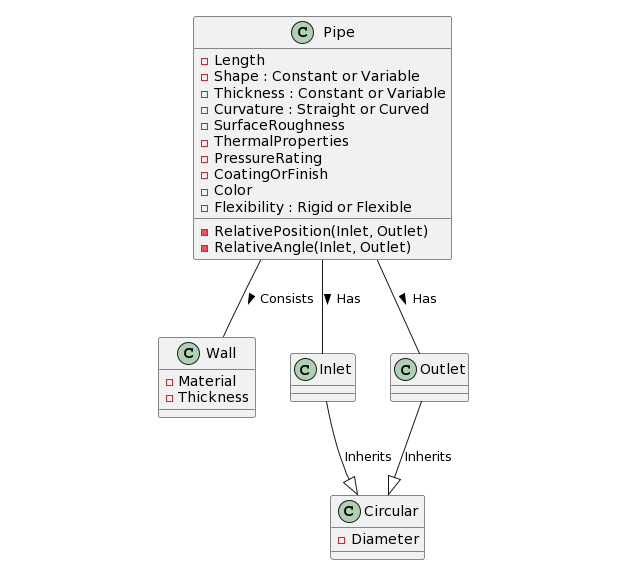
What’s more, ChatGPT demonstrated an understanding of the model and its structure when provided with one made using PlantUML syntax. This is a significant observation as it suggests that LLMs like ChatGPT can serve as a bridge to convey requirements to other building blocks of the Singularity Design paradigm architecture. These other blocks, which require specific structure and context, can thus be effectively fed with the necessary information, thereby facilitating the overall design process. This experience with ChatGPT underscores the potential of LLMs in revolutionizing the way we approach design in the engineering industry.
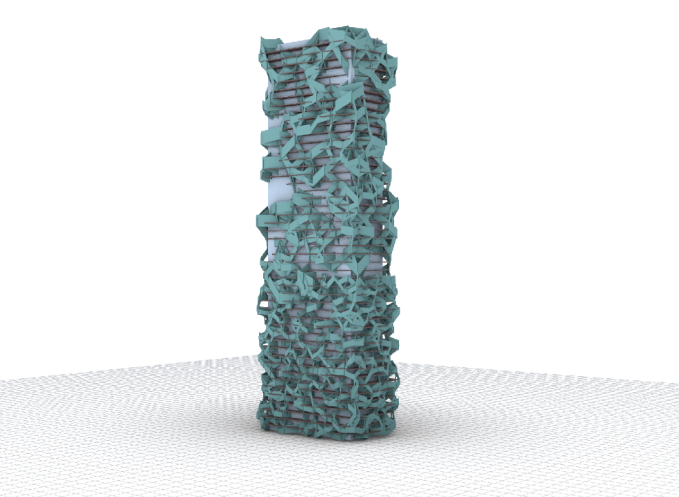
This is how you can imagine an aircraft…

…and generate different versions of it based on the model (https://doi.org/10.1016/j.aei.2012.02.002)
")
Generative Design
Having obtained our requirements, we are now prepared to progress to the next stage in the pipeline, transforming them into the desired form. However, defining this ‘desired form’ is contingent on the internal architecture of the subsequent block we employ - a form of algorithm derived through machine learning. This is a pivotal point in the workflow, and the approach to its creation will influence not only our handling of requirements but also the range of potential results we can achieve. This stage is highly adaptable in its interpretation and serves as the core of the process.
AI Aided Design
The algorithm can be trained on the execution of simple tasks during design in CAD software. For instance, requirements might be phrased as: “create 4 holes along the front side of this part”. Interestingly, there’s no need to specify the diameter and positioning of the holes. This is because our model can be trained on a database of completed operations, and the output will include all the missing details, selected based on what best fits our input. This is akin to image generation - you request a cat, and you receive a detailed image of a cat. If you desire a cat of a different color, simply submit another prompt. This exemplifies one of the features of Singularity Design - the ability to rapidly iterate until the desired result is achieved.
The example with the holes can be viewed as an initial step in the implementation of the new paradigm. In this stage, most of the work is still manually performed in CAD software, but now we have the added assistance of “AI” alongside Computer Assistance. This initial step appears straightforward as we have a known number of operations that can be executed in the given software. With sufficient data, we can train a model that will be integrated with the functions to execute them based on our requests. We take the input with requirements for the operation, identify corresponding functions, populate their parameters with values from the requirements, and for the missing parameters, the model will select what is most suitable according to its training.
AI Generated Design
However, we can further amplify this idea by shifting our training focus. Instead of instructing the algorithm on the required operations, we could train it on the outcomes - on the resultant designs themselves. Imagine 3D objects generation instead of 2D images and requirements as a prompt - sounds good. While this is a more complex task, it could potentially simplify the development of the desired design. Much like the example with the holes, it could eliminate the need for certain parameters.
This strategy mirrors topological optimization, but with a twist. Instead of setting boundaries, you establish design goals. One significant advantage of this method is the ability to create features with functions beyond the merely mechanical. This is extremely useful in creative tasks and very much in demand in architecture. When coupled with topological optimization and Computer-Aided Engineering (CAE), this strategy can lead to the creation of intricate designs in a fraction of the time.
What foundational elements fuel such a sophisticated algorithm? The crux of the matter rests within vast databases of 3D designs, meticulously cataloged and classified in great detail. Yet, the question arises: where does one acquire such a comprehensive resource? Currently, it remains an elusive quest. However, the construction of these databases is well underway, spearheaded by Computer-Aided Design (CAD) platforms that have embraced cloud computing, often offering their services gratis. Prominent examples that spring to mind include Fusion 360 and Onshape. It brings to light an old adage: if you’re not paying for the product, then you are the product. Indeed, one could embark on the journey of compiling such a database independently, but the complexity of this endeavor is vast and perhaps beyond the scope of this discussion. The key takeaway is that the raw material for this algorithmic training exists - it’s merely a matter of harnessing the right tool to process and utilize it for generative purposes.
Adaptive Flux Method
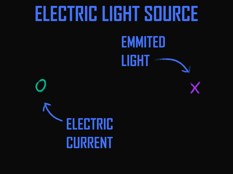
The final evolution of the block that transforms requirements into a structure or blueprint for the creation of 3D objects (or a digital twins of the desired real objects) in a workflow can be implemented with a concept of the Adaptive Flux Method as I call it. The Adaptive Flux Method centers on the mutual interactions of the requirements and how these interactions guide and mold the design.
I hope the video below can help grasp the essence. For instance, let’s create a light source powered by electricity. Input is electrical current, output is light. We’ll localize the input and output in space, where they intersect, and at this intersection, conversion occurs. That’s it! This is the finished result, as it’s a detailing of the simplest level of initial data. And with this result, one can work, integrating it into the overall system.
Later, there will be requirements for the maximum power of the converter, and requirements for the direction of lighting will emerge. These requirements will supplement the properties and alter the model’s picture. The line from the power source to the converter will be filled with properties corresponding to a conductor. A distorting element, similar to a lens, will appear in the light’s path. AI could take this information and compile a project based on it, even if we forget to specify how exactly to produce light—be it by incandescent lamp or laser. Gaps will again be filled with data deemed suitable by AI. And if something is not satisfactory, one can always specify, for instance, that a simple LED bulb is needed, and a new iteration will be ready.
The inspiration for this method came from a story about how connecting two intersecting pipes at one point in a system could halve the number of fastening elements at their ends. This is an emergence phenomenon. To achieve such a result deliberately in the traditional approach to design is nearly impossible due to the boundaries of elements I mentioned earlier. The Adaptive Flow Method strives to see requirements, not details. In the case of the pipes, using AFM, the flows with requirements for bearing structural loads will find themselves in one area, and there will be no obstacles or boundaries for their interaction if it leads to an increase in system efficiency.
This method signifies a departure from traditional design processes, injecting an element of dynamism and adaptability into the workflow. Rather than treating each requirement in isolation, the Adaptive Flux Method envisages each requirement as a distinct flow. These flows are not static; they interact with each other, responding and adapting to changes in other flows, thus creating a dynamic system.

The Adaptive Flux Method doesn’t just map these interactions, it utilizes them as drivers for the design generation. Based on the characteristics of each flow and its interactions with others, the system generates appropriate materials and components to facilitate these flows, resulting in highly efficient, resilient, and customized designs.
While the Adaptive Flux Method proposes a revolutionary approach to design processes, it does not come without its set of challenges:
-
Computational Demand: With the method heavily reliant on machine learning and extensive simulations, the computational demands are expected to be immense. The sheer complexity and detail of multiphysics simulations that the approach would need to consider to achieve optimal results could potentially necessitate highly advanced computational resources, possibly stretching beyond current capabilities.
-
Data Requirement: To train the machine learning algorithms, extensive data sets, covering a broad range of scenarios, will be required. Gathering, curating, and maintaining the relevance of these data sets pose significant challenges.
-
Rare and Extreme Cases: The reliance on simulations could limit the ability to handle extreme or rare cases. Such cases, which often play a critical role in innovative design processes, might not be adequately represented or addressed in simulation data sets. This could lead to incomplete or flawed designs.
-
Assumptions in Simulations: While simulations often rely on a set of assumptions to simplify complex real-world scenarios, the Adaptive Flux Method, in its ideal form, attempts to take into account as many details as possible. This contrast could lead to a challenging task of bridging the gap between the simplified simulation models and the detailed real-world scenarios.
-
Unpredictability: As with any process driven by AI and simulations, there can be unpredictability and a lack of transparency. The system may produce unexpected results or encounter unforeseen issues, necessitating rigorous validation and testing protocols.
In comparing the Adaptive Flux Method with modeling systems such as Simulink, several distinct differences and potential advantages can be observed. Simulink and similar modeling systems typically operate within a one-dimensional space - the dimension of time. These systems are used to model dynamic systems and their behavior over time, with their output usually being a function of time.
Simulink, OpenModelica and similar systems rely on a user-defined model, following known equations and laws of physics. On the contrary, the Adaptive Flux Method envisions a three-dimensional modeling environment that maps directly to real-world coordinates. This approach enables the modeling of requirements not just as abstract parameters, but as tangible entities that can interact within a three-dimensional space. Such interaction results in the formation of complex structures that are inherently optimized to fulfill the requirements based on their spatial relationships.
This paradigm shift from one-dimensional to three-dimensional modeling represents a significant evolution. While traditional modeling systems are excellent for mapping the progression of dynamic systems over time, they may not be inherently designed to handle the emergence of new design properties or connections that can occur in a three-dimensional space.
A primary distinction of the Adaptive Flux Method is its inherent focus on emergence, which allows for the spontaneous creation of new properties or connections as a result of the dynamic interaction between requirement fluxes. This capacity for emergence distinguishes it from many existing modeling systems, which tend to follow more rigid, pre-defined pathways and typically lack support for emergent properties.
Systems like generative design and topology optimization do support the emergence of new design properties, yet they often operate within set constraints and do not inherently respond dynamically to changing requirements. They create a myriad of design possibilities based on set parameters, but the interactions between these parameters are not typically the core focus.
However, it’s important to clarify that the Adaptive Flux Method is not a tool for visualizing design, as a block diagram is. Instead it’s seeking to generate optimized and innovative designs through the dynamic interaction of requirements within a three-dimensional space.
Arguing against this approach, a few potential flaws could be identified:
-
Complexity: This method introduces a high level of complexity. Managing and visualizing the interactions between multiple fluxes could be highly challenging.
-
Validation: Verifying and validating designs generated by such a complex and dynamic system could be difficult. There’s a risk of overlooking flaws because of the system’s inherent complexity.
To address these potential issues, it would be important to incorporate advanced visualization tools and robust testing and validation protocols into the Adaptive Flux Method.
Filtering and Reviewing
Now that we’ve explored various model generation methods, it’s time to focus on generating a set that meets our requirements. We’ll mainly focus on fully automatic model generation methods. The hybrid approach, where AI assists operations in CAD, involves a shift in workflow that closely resembles existing methods in systems engineering/MBSE, largely due to user involvement in key decisions.
Once our models are created, we can implement a filtering process. By removing models with too many geometric or other similarities, we significantly decrease the workload and allow for a more focused comparison during the evaluation stage.

The next step involves defining a solution space, which sets parameters for possible modifications to the models. These parameters can range from the thickness of the material to the color of the coating. Within this defined solution space, our set of models undergoes parametric generation.

We are then left with a diverse set of models that can be further filtered based on specific criteria before evaluation. The purpose of evaluation is to refine the solution space and possibly adjust the requirements, thereby setting the stage for another iteration.
Following a successful evaluation, the final models undergo a review and grading process to select the ultimate design. This comprehensive, layered approach ensures the generation of designs that are not only innovative and practical, but also perfectly tailored to meet specific requirements.

This work is licensed under a Creative Commons Attribuition-ShareAlike 4.0 International License .